martes, 18 de octubre de 2016

Capacidad de bombas de vacio / Capacity vacuum pumps

¿Cuál es el tamaño correcto? y ¿Cómo seleccionar la bomba?

La bomba se selecciona de acuerdo a las toneladas de refrigeración del sistema.
Por cada cfm podemos evacuar de una manera efectiva 7 toneladas de refrigeración de un sistema, entonces aplicamos una sencilla fórmula:
(Toneladas de refrigeración del sistema / 7) = CFM requeridos para evacuar el sistema.
CFM: Pies Cúbicos por Minuto
La velocidad con la que se efectúa el vacío dependerá de:
a) La altura sobre el nivel del mar (presión atmosférica). Esta es diferente en cada lugar geográfico en donde se hace el proceso del vacío.
b) La temperatura ambiente a la que está expuesto el sistema. Una técnica conocida para acelerar el tiempo del vacío es elevar la temperatura del sistema por un medio externo, ya sea a través de lámparas incandescentes o por otro método que pueda incrementar la temperatura del equipo.
c) El diámetro de las mangueras. Hacer el vacío con mangueras de 1/4 baja a una velocidad del vacío a 1.7 CFM aunque la bomba sea de una capacidad mayor. Para que obtengas la potencia completa de la bomba, debes de conectar la manguera la puerto más grande.
Vacío correcto
Para saber que llegamos al vacío correcto se requiere de un vacuómetro electrónico para medir el vacío de manera eficaz. El vacío correcto se alcanza midiendo, no por el tiempo que dejemos la bomba trabajando en el sistema, o por el sonido de la bomba. 1000 micrones equivalen a tan sólo 0,039 pulgadas de mercurio, una medición imposible de realizar con un manómetro mecánico. La única herramienta que puede medir el vacío a estos niveles es un vacuómetro electrónico. ASHRAE recomienda evacuar a menos de 1000 micrones, y una vez aislado, el sistema no debe subir por encima de los 2500 micrones durante varias horas. Para asegurar la eliminación de los dañinos vapores de agua del sistema los vacíos a los que se debe llegar: 500 micrones con Aceite mineral o Aceite Alquilbenceno ó 250 micrones con Aceite Polyol Ester.
 

What is the right size? and How to select the pump?

The pump is selected according to the tons of cooling system.
Per cfm we can effectively evacuate 7 tons of cooling system, then apply a simple formula:
(Tons of cooling system / 7) = CFM required to evacuate the system.
CFM: cfm
The speed with which the vacuum is effected depends on:
a) The height above sea level (atmospheric pressure). This is different in each geographic location where the vacuum process is done.
b) The ambient temperature at which the system is exposed. A technique known to accelerate time vacuum is to raise the temperature of the system by external means, either through incandescent lamps or other method that can increase the temperature of the equipment.
c) The diameter of the hoses. Evacuating 1/4 hoses low vacuum at a rate of 1.7 CFM although to be of higher pump capacity. So you get the full power of the pump, you must connect the hose the largest port.
Empty correct
To know that we reach the correct vacuum is required of an electronic vacuum gauge to measure the gap effectively. The correct vacuum is reached by measuring, not the time to stop the pump working on the system, or the sound of the pump. 1000 micron equals 0.039 only mercury, making measurement impossible with a mechanical manometer. The only tool that can measure the gap at these levels is an electronic vacuum gauge. ASHRAE recommends evacuate less than 1000 microns, and once isolated, the system should not rise above 2500 microns for several hours. To ensure removal of harmful water vapors system gaps that must be reached: 500 microns with mineral oil or alkylbenzene or 250 microns with Oil Polyol Ester.
 
Resultado de imagen para tipos bombas de vacio 
 
Resultado de imagen para tipos bombas de vacio 
Resultado de imagen para tipos bombas de vacio
 

Mediciòn de corriente / Current measurement

¿COMO SE MIDE LA CORRIENTE DIRECTA?
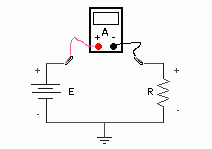
Para medir corriente directa se utiliza el multímetro como amperímetro y se selecciona, en el multímetro que estemos utilizando, la unidad (amperios) en DC (c.d.). Se revisa que los cables rojo y negro estén conectados correctamente.

Se selecciona la escala adecuada, si tiene selector de escala (si no tenemos idea de que magnitud de la corriente directa que vamos a medir, escoger laescala mas grande). Si no tiene selector de escalaseguramente el multímetro escoge la escalaautomáticamente.
Para medir una corriente con el multímetro, éste tiene que ubicarse en el paso de la corriente que se desea medir. Para esto se abre el circuito en el lugar donde la corriente a medir y conectamos el multímetro (lo ponemos en “serie”).


Si la lectura es negativa significa que la corriente en el componente, circula en sentido opuesto al que se había supuesto, (normalmente se supone que por el cable rojo entra la corriente al multímetro y por el cable negro sale). En algunas ocasiones no es posible abrir el circuito para colocar el amperímetro. En estos casos, si se desea averiguar la corriente que pasa por unelemento, se utiliza la Ley de Ohm.


Se mide la tensión que hay entre los terminales del elemento por el cual pasa la corriente que se desea averiguar y después, con la ayuda de la Ley de Ohm (V = I x R), se obtiene la corriente (I = V/R). Para obtener una buena medición, se debe tener los valores exactos tanto del voltaje como de la resistencia.
Otra opción es utilizar un amperímetro de gancho (que puede ser un amperímetro analógico o un amperímetro digital) que permite obtener la corriente que pasa por un circuito sin abrirlo. Este dispositivo, como su nombre lo indica, tiene un gancho que se coloca alrededor del conductor por donde pasa la corriente y mide el campo magnético alrededor de él. Esta medición es directamente proporcional a la corriente que circula por el conductor y que se muestra con una aguja o pantalla.


Notas:
  • Multímetro = VOM = Tester = Polímetro
  • Amperímetro se llama, en este caso, al multímetro preparado para medir corriente.


How to measure direct current?

To measure DC multimeter as an ammeter is used and in the meter we are using, select the drive (amps) in DC (D.C.). We review the red and black cables are properly connected.
the appropriate scale is selected, if you have scale selector (if we have no idea that magnitude of the direct current that we measure, choose larger scale will test). If no selector escalaseguramente the multimeter chooses escalaautomáticamente.
To measure a current with the meter, it must be located in the passage of the current to be measured. For this, the circuit is opened at the place where the current to be measured and connect the multimeter (put it in "series").
If the reading is negative means that the current component, flowing in the opposite direction than had been assumed, (usually it is assumed that the red current cable enters the multimeter and the black wire out). Sometimes it is not possible to open the circuit to place the ammeter. In these cases, if you want to find out the current through unelemento, Ohm's Law is used.
Measure direct current (DC) - Electronics Area
the tension between the terminals of the element through which passes the current sedesea find and then, with the help of Ohm's Law (V = I x R) is measured, the current (I = V / R) is obtained . For a good measurement, it must be the exact values ​​of the voltage as much resistance.
Another option is to use an ammeter hook (which may be an analog or digital ammeter ammeter) for obtaining the current through a circuit without opening it. This device, as its name implies, has a hook that is placed around the conductor through which the current and measures the magnetic field around it. This measurement is directamenteproporcional the current flowing through the conductor and shown with a needle or screen.
Notes:
Multimeter VOM = = = Multimeter Tester
Ammeter is called, in this case, the multimeter prepared to measure current.

 Resultado de imagen para medicion de corriente

Tipos de tubos para refrigeraciòn / Types of pipe for cooling

TIPOS DE TUBOS 


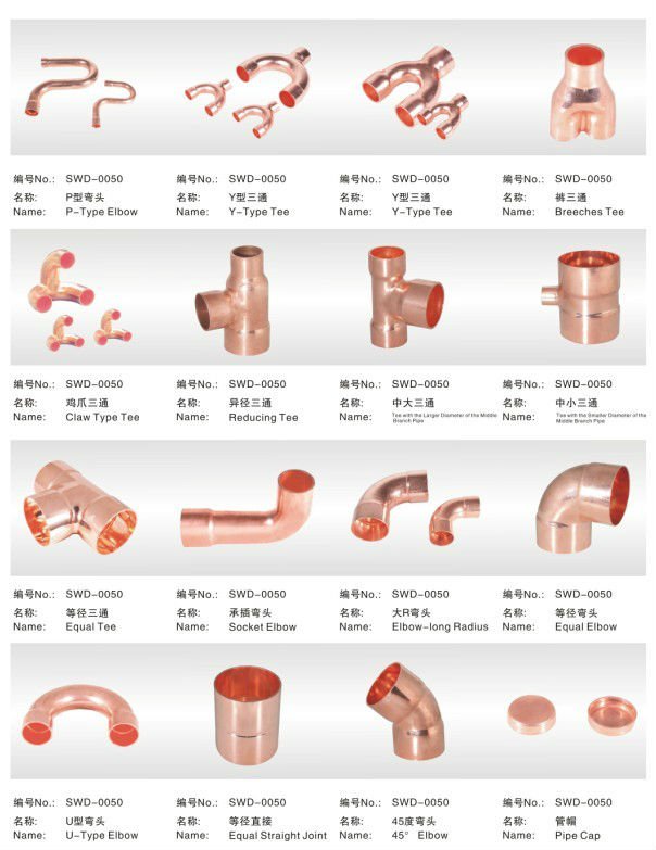
La mayor parte del tubo que se usa en acondicionamiento de aire está hecho de cobre.  Sin embargo, hoy en día el aluminio se usa mucho para fabricar los circuitos internos sé los serpentines del evaporador y condensador, aunque no se ha extendido su uso en fabricación en el campo porque no se puede trabajar con tanta facilidad como el cobre, y es más difícil de soldar.
La tubería de acero se usa para armar los sistemas de refrigeración muy grandes en los que se necesitan tubos de 6 pulg de diámetro o mayores.  En la refrigeración moderna no se usan conexiones roscadas de tubo de acero, porque no se puede hacer herméticas.
Estos sistemas son soldados, y cuando se necesita conectar al equipo o se necesitan uniones de servicio se usan conexiones atornilladas.
El término tubing se aplica en general a materiales de pared delgada, que se unen mediante sistemas que no sean de rosca cortada en la pared del tubo.  Por otro lado, el término tubo común y corriente es el que se aplica a materiales con pared gruesa, como por ejemplo hierro y acero, en los cuales se pueden cortar roscas en la pared y que se unen mediante conexiones que se atornillan en el tubo.
Estos tubos también se pueden soldar.  Otra diferencia entre “tubing” y tubo es el método de medición de tamaño.  Los tamaños de “tubing” se expresan en términos del diámetro exterior (DE), y los del tubo se expresan como diámetros nominales interiores (DI).  
“TUBING” DE COBRE
Este “tubing”1 se usa en la mayor parte de los sistemas domésticos de refrigeración, y es cobre especialmente reconocido.  Cuando se forma el tubo de cobre tiene una tendencia a endurecerse, y esta tendencia podría originar grietas en los extremos del “tubing” cuando se avellanan o se aplanan.
El cobre se puede reblandecer por calentamiento hasta que su superficie tenga color azul, y dejándolo enfriar.  A este proceso se le llama recocido y se hace en fábrica.
El “tubing” de cobre que se usa en refrigeración y acondicionamiento de aire sé llama_tubing ACR, que quiere decir que se usa en trabajos de refrigeración y ante acondicionado, y que se ha fabricado y procesado especialmente para este objeto.  El “tubing” ACR tiene nitrógeno a presión para evitar la entrada de aire, humedad y polvo, y también para dar máxima protección contra los óxidos perjudiciales que se forman normalmente durante el latonado.
Los extremos están taponados, y los tapones se deben volver a poner después de cortar un tramo del “tubing”.

Clasificación del “tubing” de cobre
El “tubing” de cobre tiene tres clasificaciones:  K, L y M, que se basan en los espesores de pared:
K:  pared gruesa, aprobado para refrigeración y aire acondicionado
L:  pared media, aprobado para refrigeración y aire acondicionado
M: pared delgada; no se usa en sistemas de refrigeración.
El “tubing” M de pared delgada no se usa en tuberías de refrigerante a presión, porque no tiene el espesor de pared necesario para cumplir con los reglamentos de seguridad; sin embargo, se usa en tuberías de agua, drenado de condensados y otras necesidades relacionadas con el sistema.
El “tubing” K de pared gruesa se emplea en usos especiales, cuando se esperan condiciones excepcionales de corrosión.  El tipo L es el que se usa con más frecuencia para aplicaciones normales en refrigeración.  La figura R5-2 muestra una tabla de especificaciones para “tubing” tipos K y L.  Ambos tipos se consiguen en variantes de extrusión suave o dura.
“Tubing” de cobre extruido suave
Como su nombre lo dice, se recuece para hacer que el tubo sea más flexible y fácil de doblar y conformar.  Se consigue en el comercio en tamaños de ⅛″ a 1 ⅝″ DE y se vende con frecuencia en rollos de 7.5, 15 y 30 metros.  Los rollos se deshidratan y sellan en fábrica.  El “tubing” de cobre suave se puede soldar o usar con conexiones abocinadas o mecánicas de otro tipo.
Como se dobla y se conforma con facilidad debe sujetarse con abrazaderas u otros componentes para soportar su propio peso.
1N de T.: En español no se diferencia entre tubo “tubing” y tubo “pipe”; el contexto es lo que define lo que se trata.  Sin embargo, en este capítulo sí haremos la distinción, y en el resto del libro sólo usaremos la palabra “tubing” cuando sea necesario aclarar para que el lector no se confunda.
     
                         DIÁMETRO
                      Exterior,   Interior,             Espesor de                Weight per             
Tipo                 Pulg.          Pulg.                Pared, pulg                  Foot (lb)
                  
K                        ½            0.402                      0.049                          0.2691
                           ⅝            0.527                      0.049                          0.3437
                           ¾            0.652                      0.049                          0.4183
                           ⅞            0.745                      0.065                          0.6411
                         1⅛            0.995                      0.065                          0.8390
                         1⅜            1.245                      0.065                          1.037
                         1⅝            1.481                      0.072                          1.362
                         2⅛            1.959                      0.083                          2.064
                         2⅝            2.435                      0.095                          2.927
                         3⅛            2.907                      0.190                          4.003
                         3⅝            3.385                      0.120                          5.122
L                        ½             0.430                      0.035                          0.1982
                          ⅝             0.545                      0.040                          0.2849
                          ¾             0.666                      0.042                          0.3621
                          ⅞             0.785                      0.045                          0.4518
                        1⅛             1.025                      0.050                          0.6545
                        1⅜             1.265                      0.055                          0.8840
                        1⅝             1.505                      0.060                          1.143
                        2⅛             1.985                      0.070                          1.752
                        2⅝             2.465                      0.080                          2.479
                        3⅛             2.945                      0.090                          3.326
                        3⅝             3.425                      0.100                          4.292
                          
                                                         
Su aplicación más frecuente es para tamaños de tuberías de ¼″ a ¾″ DE.  
Cuando el diámetro es mayor que, se hace difícil él darle forma.
                   
“Tubing” de cobre extruido duro
Este “tubing” también se usa mucho en sistemas comerciales de refrigeración y aire acondicionado.  A diferencia del extruido suave, es duro y rígido y tiene la forma de tramos rectos.  Se debe usar con conexiones formadas para dar los cambios de dirección y dobleces necesarios.  A causa de su construcción rígida es más auto soportante y necesita de pocos soportes.  Sus diámetros van de ⅜″ a más de 6″.

El “tubing” extruido duro se vende en tramos normales de 6 m que están deshidratados, cargados con nitrógeno y taponados en ambos extremos para mantener una condición interna limpia y libre de humedad.  El empleo de “tubing” extruido duro se asocia con más frecuencia con tamaños mayores de tubería, de ⅞″ o más.


TYPES OF PIPES


Most of the tube used in the air conditioning is made of copper. However, nowadays aluminum is widely used to manufacture the internal circuits the evaporator coils and condenser, but has not spread use in manufacture in the field because you can not work as easily as copper, and is more difficult to weld.
The steel pipe is used to build very large systems where cooling pipes 6 inches in diameter or larger are required. In modern cooling unthreaded steel pipe connections are used, because you can not airtight.
These systems are soldiers, and when you need to connect to equipment or service unions are needed bolted connections are used.
The term applies tubing generally thin-walled materials, which are joined by systems other than cut thread in the tube wall. Furthermore, the term ordinary tube is applied to materials with thick wall, such as iron and steel, in which can be cut threads in the wall and which are joined by connections which are screwed into the tube .
These pipes can also be welded. Another difference between "tubing" and is the tube size measurement method. The sizes of "tubing" are expressed in terms of outside diameter (OD) and pipe interiors are expressed as nominal diameters (DI).
"TUBING" COPPER
This "tubing" 1 is used in most domestic refrigeration systems and is particularly recognized copper. When formed copper tube has a tendency to stiffen, and this trend could result in the ends of cracks "tubing" when countersink or flattened.
Copper can be softened by heating until its surface has blue, and allowing it to cool. This process is called annealing and is factory.
The "tubing" copper used in refrigeration and air conditioning llama_tubing ACR, which means that work is used in refrigeration and conditioning before, and which is manufactured and processed specifically for this purpose. The "tubing" ACR nitrogen-pressurized to prevent ingress of air, moisture and dust, and also to give maximum protection against harmful oxides are usually formed during brazing.
The ends are plugged, and plugs should be put back after cutting a section of "tubing".

Classification of "tubing" copper
The "tubing" copper has three classifications: K, L and M, which are based on wall thickness:
K: thick-walled, approved for refrigeration and air conditioning
L: half wall, approved for refrigeration and air conditioning
M: thin wall; not used in refrigeration systems.
The "tubing" M thin wall is not used in pressurized refrigerant pipes, because it has the wall thickness necessary to comply with safety regulations; however, it is used in water pipes, drain condensate and other needs related to the system.
The "tubing" K thick-walled is used in special applications where exceptional corrosion conditions are expected. The type L is used more frequently for normal refrigeration applications. The R5-2 shows a table of specifications for "tubing" types K and L. Both variants are available in soft or hard extrusion.
"Tubing" soft extruded copper
As its name says, it is annealed to make the tube more flexible and easy to bend and shape. It is available commercially in sizes from ⅛ "to 1 ⅝" DE and is frequently sold in rolls of 7.5, 15 and 30 meters. The rolls are dehydrated and sealed at the factory. The "tubing" soft copper can be welded or use with splayed or other mechanical connections.
As it bends and conforms easily be secured with clamps or other components to support its own weight.
1N T .: In Spanish does not differentiate between tube "tubing" and tube "pipe"; the context is what defines what it is. However, this chapter will distinguish itself, and the rest of the book we will use only the word "tubing" when necessary to clarify that the reader is not confused.                         
                                                          
Its most common application is for pipe sizes from ¼ "to ¾".
When the diameter is greater than, it becomes difficult to shape.
                    
"Tubing" hard extruded copper
This "tubing" is also widely used in commercial refrigeration systems and air conditioning. Unlike the soft extrudate, it is hard and rigid and has the form of straight sections. It should be used with connections formed to give direction changes and bends necessary. Because of their more rigid construction it is self-supporting and requires few supports. Their diameters range from ⅜ "to more than 6".
The "tubing" hard extruded sold in normal sections 6 m that are dehydrated, loaded with nitrogen and capped at both ends to keep clean and free internal moisture condition. The use of "tubing" extruded hard more often associated with larger sizes of pipe, ⅞ "or more.
 
 Resultado de imagen para tipos de tuberias para refrigeracion

Ohms, amperes y volts / ohmios, amperios Y voltios

OHM:

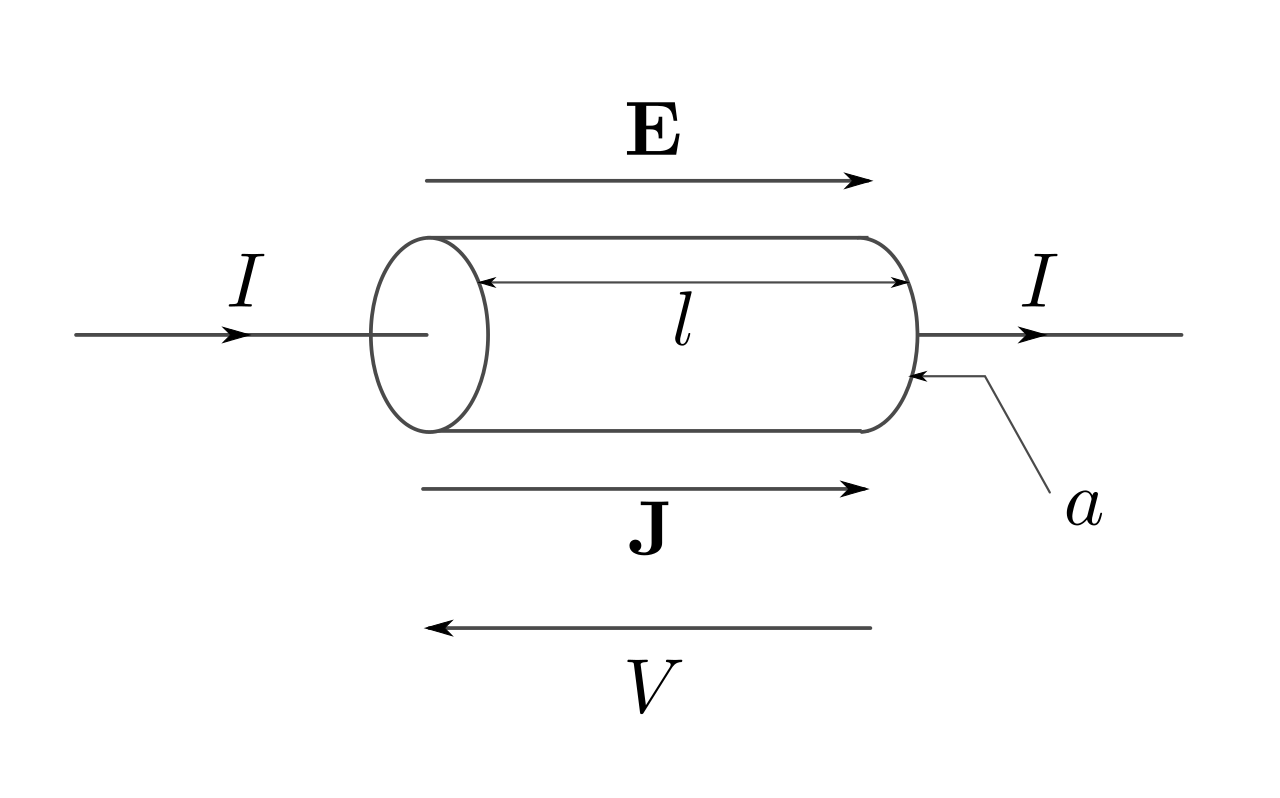
Se define a un ohmio como la resistencia eléctrica que existe entre dos puntos de un conductor, cuando una diferencia de potencial constante de 1 voltio aplicada entre estos dos puntos, produce, en dicho conductor, una corriente de intensidad de 1 amperio (cuando no haya fuerza electromotriz en el conductor). Se representa por la letra griega mayúscula omega (Ω). También se define como la resistencia eléctrica que presenta una columna de mercurio de 5,3 cm de altura y 1 mm² de sección transversal a una temperatura de 0 °C.
Estándar      Unidades derivadas del Sistema Internacional
Magnitud     Resistencia eléctrica
Símbolo       Ω
Nombrada en honor de   Georg Simon Ohm
Equivalencias
Unidades básicas del Sistema Internacional  1 Ω = V / A


AMPER:
El amperaje no es otra cosa que la fuerza o la potencia en una corriente eléctrica circulando entre dos puntos, estos son el negativo y el positivo a través de un conductor o cable eléctrico. La corriente eléctrica circula del negativo hacia el positivo.
La forma de saber que amperaje circula por una corriente eléctrica es conectado en serie un amperémetro, para esto debe de haber una carga entre el negativo y el positivo, por ejemplo, un receptor de radio, una lavadora de ropa, etc.
El amperaje en un circuito eléctrico se ha comparado con un flujo de agua por un conducto, cuanto más caudal de agua, mayor presién, otro factor que influye es el grosor del conducto. si el conducto es reducido el agua contiene más presión pero su caudal será menor. Si por el contrario, el conducto es mayor, la cantidad de agua será, por lo mismo mayor pero a menor presión. Lo mismo sucede con un conductor eléctrico, si su calibre (grueso) es reducido, la corriente encontrará resistencia u oposión a su paso, si el calibre es mayor, fluirá de forma libre con menor resistencia.

VOLT:
El voltio, o volt, por símbolo V, es la unidad derivada del Sistema Internacional para el potencial eléctrico, la fuerza electromotriz y la tensión eléctrica. Recibe su nombre en honor a Alessandro Volta, quien en 1800 inventó la pila voltaica, la primera batería química.


English

OHM:

It is set to one ohm as electrical resistance between two points of a conductor, when a constant potential difference of one volt applied between these two points, produces, at said driver, a current intensity of 1 ampere (when no electromotive force in the conductor). It is represented by the Greek letter capital omega (Ω). It is also defined as electrical resistance that presents a mercury column of 5.3 cm and 1 mm² cross section at a temperature of 0 ° C.
Standard SI derived unit
Magnitude Electrical resistance
symbol Ω
Named in honor of Georg Ohm
equivalences
SI base unit 1 Ω = V / A


AMPER:
The amperage is nothing but force or power an electric current flowing between two points, these are the negative and positive through a conductor or electric cable. The electric current flows from negative to positive.
The way to know that amperage flowing through an electric current is connected in series a amperémetro, for this must have a charge between the negative and positive, for example, a radio receiver, a washing machine, etc.
Amperage in an electrical circuit has been compared to a water flow through a duct, the more water flow, greater presién, another factor is the thickness of the duct. if the duct is reduced water contains more pressure but its volume will be lower. If, however, the conduit is greater, the amount of water will, therefore higher but lower pressure. The same applies to an electrical conductor, if your gauge (thickness) is reduced, the current strength or oposión find its path, the size is increased, it will flow freely with less resistance.

VOLT:

The Volt, or volt per symbol V, is the derivative unit of the International System for the electric potential, electromotive force and voltage. It is named in honor of Alessandro Volta, who in 1800 invented the voltaic pile, the first chemical battery.
 
 
Resultado de imagen para OHM:It is set to one ohm as electrical resistance between two points of a conductor, when a constant potential difference of one volt applied between these two points, produces, at said driver, a current intensity of 1 ampere (when no electromotive force in the conductor). It is represented by the Greek letter capital omega (Ω). It is also defined as electrical resistance that presents a mercury column of 5.3 cm and 1 mm² cross section at a temperature of 0 ° C.Standard SI derived unitMagnitude Electrical resistancesymbol ΩNamed in honor of Georg OhmequivalencesSI base unit 1 Ω = V / AAMPER:The amperage is nothing but force or power an electric current flowing between two points, these are the negative and positive through a conductor or electric cable. The electric current flows from negative to positive.The way to know that amperage flowing through an electric current is connected in series a amperémetro, for this must have a charge between the negative and positive, for example, a radio receiver, a washing machine, etc.Amperage in an electrical circuit has been compared to a water flow through a duct, the more water flow, greater presién, another factor is the thickness of the duct. if the duct is reduced water contains more pressure but its volume will be lower. If, however, the conduit is greater, the amount of water will, therefore higher but lower pressure. The same applies to an electrical conductor, if your gauge (thickness) is reduced, the current strength or oposión find its path, the size is increased, it will flow freely with less resistance.VOLT:The Volt, or volt per symbol V, is the derivative unit of the International System for the electric potential, electromotive force and voltage. It is named in honor of Alessandro Volta, who in 1800 invented the voltaic pile, the first chemical battery.Resultado de imagen para OHM:It is set to one ohm as electrical resistance between two points of a conductor, when a constant potential difference of one volt applied between these two points, produces, at said driver, a current intensity of 1 ampere (when no electromotive force in the conductor). It is represented by the Greek letter capital omega (Ω). It is also defined as electrical resistance that presents a mercury column of 5.3 cm and 1 mm² cross section at a temperature of 0 ° C.Standard SI derived unitMagnitude Electrical resistancesymbol ΩNamed in honor of Georg OhmequivalencesSI base unit 1 Ω = V / AAMPER:The amperage is nothing but force or power an electric current flowing between two points, these are the negative and positive through a conductor or electric cable. The electric current flows from negative to positive.The way to know that amperage flowing through an electric current is connected in series a amperémetro, for this must have a charge between the negative and positive, for example, a radio receiver, a washing machine, etc.Amperage in an electrical circuit has been compared to a water flow through a duct, the more water flow, greater presién, another factor is the thickness of the duct. if the duct is reduced water contains more pressure but its volume will be lower. If, however, the conduit is greater, the amount of water will, therefore higher but lower pressure. The same applies to an electrical conductor, if your gauge (thickness) is reduced, the current strength or oposión find its path, the size is increased, it will flow freely with less resistance.VOLT:The Volt, or volt per symbol V, is the derivative unit of the International System for the electric potential, electromotive force and voltage. It is named in honor of Alessandro Volta, who in 1800 invented the voltaic pile, the first chemical battery.

Tipos de compresores / Types of compressors

Tipo de compresores de aire acondicionado según su fabricación
Compresor hermético
El compresor hermético generalmente suele ser utilizado en instalaciones pequeñas y de baja potencia ya que tienen un menor coste y utilizan un menor espacio dentro de la unidad, este tipo de compresor es refrigerado directamente por el propio refrigerante y no requieren de transmisiones entre el motor y el propio compresor. Por contra, cuando un compresor hermético se avería, la reparación de este resulta más cara al no poder acceder al interior de este de manera fácil, generalmente este tipo de compresor es sustituido y no reparado.
Compresor semihermético
El compresor semihermético es utilizado habitualmente en instalaciones de media potencia, estos tienen el motor y el compresor instalados dentro de un recipiente a presión y accesibles para su reparación en caso de avería. Estos se pueden subdividir en dos clases, los enfriados por aire que suelen ser de baja potencia y los enfriados por aspiración.
Compresor abierto
Este tipo de compresores de aire acondicionado al ser más versátiles y accesibles se suelen utilizar en medias y grandes potencias, los compresores abiertos son totalmente accesibles para su reparación y la transmisión se realiza en el exterior por medio de correas por lo que a causa de esto suelen presentar más problemas de vibraciones y es necesario una correcta alineación y tensión de las mismas.
Tipos de compresores de aire acondicionado según su funcionamiento / Tecnología
Compresor alternativo de pistón
Estos se basan en la transformación del un movimiento rotativo en otro alternativo similar a los motores de un coche pero en sentido inverso, están formados por una cámara de compresión en forma de cilindro y un pistón que se desplaza interiormente por dicho cilindro. El pistón está unido a
Funcionamiento de un compresor alternativo de pistón.
Compresor alternativo de pistón.
través de una biela de transmisión a un motor accionador. Al girar el motor, la biela describe un movimiento de vaivén, succionando el gas de entrada a través de la válvula de admisión cuando retrocede el pistón, comprimiendo el gas cuando avanza el pistón y expulsando el gas a través de la válvula de escape cuando el pistón llega al final de su recorrido.
Los segmentos colocados en el émbolo aseguran la estanquidad entre éste y el cilindro, separando la alta presión (interior del cilindro) de la baja presión (cárter).
En los compresores pequeños en lugar de segmentos se utilizan pistones con ranuras, que aseguran la estanquidad por las importantes pérdidas de carga que sufre el gas al atravesarlas y por la película creada por el aceite de lubricación.
Compresor rotativo de pistón rodante
En general, los compresores de aire acondicionado rotativos poseen acoplamiento directo del motor y no tienen válvulas de admisión, circulando el gas siempre en el mismo sentido. Admiten elevadas relaciones de compresión ya que el abundante aceite del mismo ayuda a lubricar y además ayuda a eliminar el calor producido por el propio compresor. Estos están sujetos a mucha menos vibración mecánica que los compresores alternativos.
En los compresores de pistón rodante, el eje motor y el eje del estator son concéntricos, mientras que el eje del rotor es excéntrico. Al deslizar el rotor sobre el estator se establece entre ellos un contacto, que en el estator tiene lugar a lo largo de todas y cada una de sus generatrices, mientras que en el rotor solo a lo largo de una, la correspondiente a la máxima distancia al eje motor.
Compresor rotativo de pistón rodante.
La admisión del vapor se efectúa a través de la lumbrera de admisión y el escape a través de la válvula de escape. El vapor aspirado en el compresor, que llena el espacio comprendido entre el rotor y el estator, se comprime de forma que, al girar, disminuye progresivamente su espacio físico hasta que alcanza la presión existente  en la válvula de escape, que en ese momento se abre, entonces tiene lugar la expulsión o descarga del vapor.
Compresor rotativo de tornillo
El compresor de tornillo utiliza un doble conjunto de rotores (macho y hembra). El rotor macho tiene usualmente 4 lóbulos que engranan dentro de los 6 alvéolos del rotor hembra (disposición 4 + 6), hallándose este rotor accionado por el primero y siendo los sentidos de giro opuestos. Otras variantes especiales son por ejemplo la 5 + 7.
El gas, debido al giro queda prisionero entre los espacios de los rotores, siendo transportado de un extremo al otro del engranaje donde se hallan la admisión y el escape.
Cada una de las cámaras de trabajo se comporta como si el cilindro fuese un compresor alternativo, donde cada diente del rotor conductor hace las veces de pistón, que primero cierra y después comprime el volumen inicialmente atrapado, por lo que un compresor helicoidal no es sino un compresor alternativo de seis cilindros helicoidales, en el que se han eliminado el cigüeñal, el espacio residual y las válvulas de admisión y escape.
Rotores de compresor de tornillo.
Partes de un compresor de tornillo.
Funcionamiento de un compresor de tornillo.
El gas es comprimido de un modo continuo por los rotores hasta que los lóbulos están engranados totalmente. Esto elimina la indeseable condición existente en los compresores alternativos, donde el gas en el volumen de holgura entre el pistón y la parte superior del cilindro se reexpande por el interior del cilindro, dando lugar a una reducción del rendimiento volumétrico y a un incremento en el consumo de potencia.
Una característica esencial en los compresores de aire acondicionado de tornillo es la ausencia de toda válvula tanto de descarga como de aspiración. Por el contrario, requieren de un alto grado de calidad en las tolerancias, lo cual supone elevados costes de fabricación. La relación de compresión interna está determinada por la forma de los orificios de aspiración y descarga.
Compresor scroll o rotativo de espiral
El compresor Scroll utiliza dos piezas en forma de espiral, una fija (la superior) y la otra móvil (inferior) accionada por el eje del motor. El centro de rotación de la espiral móvil está decalada en relación con el de la espira fija y superior con una excentricidad “e” llamada “radio orbital” que permite la compresión volumétrica de los vapores aspirados.
Funcionamiento de compresor Scroll.
La espiral inferior no describe un movimiento rotativo, sino que se trata de un movimiento giratorio de traslación. Entre ambas piezas (espiral fija y móvil) van creando desde la boca de admisión y de manera continua una cámara de compresión de volumen decreciente por lo que la presión va aumentando. Al final del recorrido del gas y cuando el volumen de la cámara de compresión es mínima, éste es expulsado por la salida de expulsión. En la descarga existe una válvula de retención que evita el retorno de gas a alta presión hacia la parte de baja presión a la parada de la máquina.
Actualmente se están incorporando a los compresores de aire acondicionado scroll variadores de frecuencia para la regulación de la capacidad, incidiendo sobre la velocidad de giro del compresor (inverter).
Compresor centrífugo o turbocompresor
El compresor centrífugo utiliza la fuerza centrífuga provocada por la gran velocidad periférica en que el fluido sale de los álabes del rotor, velocidad que al pasar seguidamente a través de un difusor con la consiguiente caída de velocidad, obtiene como contrapartida un aumento de la presión. Las velocidades normales del motor utilizado en los compresores alternativos, espiral y de tornillos son de unas 3.000 rpm. Para algunos compresores centrífugos de una sola etapa, con caja de engranajes, se utilizan velocidades de 30.000 rpm. Por tanto, son máquinas de alta velocidad capaces de manejar volúmenes muy grandes de gas refrigerante con bajas relaciones de compresión. La caja de engranajes tiene dos engranajes: el engranaje motor, más grande, y el engranaje accionado, que se mueve más rápido.
Si la presión de descarga aumenta demasiado o la presión de vaporización baja demasiado, el compresor no puede resistir la diferencia de presión y deja de bombear. El motor y el compresor siguen girando, pero el refrigerante deja de moverse desde el lado de baja presión al de alta presión del sistema. El compresor y el motor no se verán dañados salvo que se dejen en este estado de sobrepresión mucho tiempo.
Los fluidos frigorígenos utilizados son casi siempre los de tipo halogenado, aunque en las industrias petrolíferas y químicas se utilizan muy frecuentemente, en los compresores centrífugos, metano, propano, etileno y propileno.
Su gama de potencia frigorífica se extiende de 350 kW a 12.000 kW y las temperaturas de vaporización pueden variar de +10 C a -160 C. Se utilizan para climatización como enfriadoras de agua.

Type air conditioning compressors by manufacturing


Hermetic Compressor
The hermetic compressor generally usually used in small, low-power installations because they have a lower cost and use less space within the unit, this type of compressor is directly cooled by the refrigerant itself and require no transmissions between the engine and the compressor itself. By contrast, when a hermetic compressor fails, this repair is more expensive unable to access the inside of this easily, usually this type of compressor is replaced, not repaired.
Semi-hermetic Compressor
The semi-hermetic compressor is typically used in medium power installations, they have the motor and compressor installed inside a pressure vessel and accessible for repair in case of failure. These can be divided into two classes, the cooled air are usually low power and cooled by suction.
Open Compressor
This type of air conditioning compressors to be more versatile and accessible are usually used in medium and large powers, open compressors are fully accessible for repair and transmission is performed abroad by straps so because of this usually they have more vibration problems and need proper alignment and tension of them.

Types of air conditioning compressors according to their performance / Technology


reciprocating piston compressor
These are based on the transformation of rotary motion similar to a car engines alternative but in reverse, are formed by a compression chamber into a cylinder and a piston which moves inwardly by said cylinder. The piston is attached to

Operation of a reciprocating compressor piston.
reciprocating piston compressor.
through a connecting rod transmission to a drive motor. By turning the engine, the crank describes a reciprocating movement, sucking the gas inlet through the intake valve when backing the piston, compressing the gas when the piston advances and expelling the gas through the exhaust valve when the piston reaches the end of its route.
The segments in the plunger as seals between it and the cylinder separating the high pressure (inside the cylinder) of the low pressure (pan).
In small compressors instead of piston segments with slots, as seals for the substantial losses suffered by the gas to pass through them and the film created by the lubricating oil used.

Rolling piston rotary compressor
In general, air conditioning compressors have direct coupling rotary engine and have no intake valves, the gas circulating always in the same direction. Support high compression ratios as the same abundant oil helps lubricate and helps to remove the heat produced by the compressor itself. These are subject to much less mechanical vibration than reciprocating compressors.
In rolling piston compressors, the motor shaft and the stator are concentric, while the rotor is eccentric axis. By sliding the rotor on the stator is set including a contact in the stator occurs along each and every one of its generatrices, while the rotor only along one, corresponding to the maximum distance the mainshaft.
Rolling piston rotary compressor.
Admission of steam is performed through the intake port and exhaust through the exhaust valve. The vapor sucked into the compressor, filling the space between the rotor and stator, is compressed so that, when rotating, gradually decreases its physical space until it reaches the pressure in the exhaust valve, which at that time open, then the expulsion or steam discharge takes place.

Rotary screw compressor
The screw compressor uses a double set of rotors (male and female). The male rotor lobes usually 4 engaging within 6 alveoli of the female rotor (disposition 4 + 6), being this rotor driven by the first and still the opposite directions of rotation. Other special variants are for example the 5 + 7.

Gas, due to the rotation is caught between the spaces of the rotors, being transported from one end to the other gear where the intake and exhaust are.

Each of the working chambers behaves as if the cylinder was a reciprocating compressor, wherein each rotor tooth driver acts as piston, which first closes and then compresses the volume initially trapped, so a scroll compressor is but a reciprocating compressor six helical cylinder in which the crankshaft have been removed, the residual space and the exhaust and intake valves.

Screw compressor rotors.
Parts of a screw compressor.
Operation of a screw compressor.
The gas is compressed in a continuous manner by the rotors until the lobes are fully engaged. This eliminates the undesirable condition existing in reciprocating compressors, where the gas in the clearance volume between the piston and the top of the cylinder is re-inflates inside the cylinder, resulting in a reduction in volumetric efficiency and an increase in consumption power.
An essential feature in the air conditioning compressors screw is the absence of any valve both download and suction. By contrast, they require a high degree of quality tolerances, which means high manufacturing costs. Internal compression ratio is determined by the shape of the suction holes and discharge.

Scroll compressor or rotary spiral
The scroll compressor utilizes two spiral pieces, one fixed (the top) and the other mobile (lower) driven by the motor shaft. The center of rotation of the movable scroll is offset relative to the fixed scroll with an eccentricity and top "and" called "orbital radius" that allows the volumetric vapor compression aspirates.

Scroll compressor operation.
The lower spiral does not describe a rotating movement, but is a rotary translational movement. Between both parts (fixed and mobile spiral) are created from the inlet and continuously a compression chamber volume decreasing so the pressure increases. At the end of travel of the gas and when the volume of the compression chamber is minimal, it is ejected from the ejection outlet. In the discharge check valve which prevents the return of high pressure gas to the low pressure side to the machine stop there.
Currently being incorporated into the air conditioning compressors scroll frequency drives for capacity regulation, focusing on the rotational speed of the compressor (inverter).

centrifugal supercharger or turbocharger
The centrifugal compressor uses centrifugal force caused by high peripheral speed at which the fluid exits the rotor blades, speed as then passed through a diffuser with consequent drop speed, obtained as counterpart an increased pressure. Normal engine speeds used in reciprocating compressors, spiral and screw are about 3,000 rpm. For some centrifugal compressors single stage, with gearbox, 30,000 rpm speeds are used. Therefore, high speed machines are capable of handling very large volumes of refrigerant gas with low compression ratios. The gearbox has two gears: the gear motor, larger, and the driven gear, moving faster.

If the discharge pressure increases or pressure too low vaporization too, the compressor can not resist the pressure difference and stops pumping. The motor and compressor continue rotating, but the refrigerant stops moving from the low pressure side to the high pressure system. The compressor and motor undamaged unless left in this state overpressure will be long.

Refrigerant fluids used are almost always the halogen type, although in the oil and chemical industries methane, propane, ethylene and propylene are most frequently used in centrifugal compressors.
Its range of cooling power 350 kW extends to 12,000 kW and vaporization temperatures may vary from +10 C to -160 C. are used for air conditioning as water.
 
Resultado de imagen para tipos de compresores de refrigeracion